Heat Exchanger Troubleshooting: How to Identify Fouling, Performance Loss, and Debottlenecking Opportunities
When a Heat Exchanger No Longer Delivers Its Design Performance
Heat exchangers are among the most important pieces of equipment in process industries. From chemical manufacturing and petroleum refining to food processing, pharmaceuticals, power generation, and water treatment, their performance directly influences product quality, energy consumption, production capacity, equipment reliability, and operating cost.
Yet, heat exchangers rarely maintain their original performance indefinitely. A unit that once achieved the required outlet temperature may gradually lose its thermal effectiveness. Cooling water consumption may increase, pressure drop may rise, product throughput may decline, or operators may find themselves pushing pumps, compressors, and control valves closer to their operating limits to maintain production.
These symptoms are often attributed to fouling, but fouling is only one possible explanation. Performance deterioration can also result from inadequate flow distribution, changing process conditions, control-system limitations, non-condensable gases, air binding, bypassing, maldistribution, incorrect instrumentation, or an exchanger that was inadequately sized for the actual operating duty.
The challenge is therefore not simply to clean the exchanger or increase the flow rate. It is to determine why the exchanger is underperforming, quantify the extent of the performance loss, identify the actual operating constraint, and select the most economically and technically appropriate corrective action.
A systematic troubleshooting approach can reveal opportunities to recover lost capacity, reduce utility consumption, prevent unnecessary maintenance, and postpone or avoid capital-intensive equipment replacement.
1. Understanding Heat Exchanger Performance Before Diagnosing Failure
A heat exchanger transfers thermal energy between two or more fluid streams without necessarily mixing them. Its performance depends on the heat-transfer area, overall heat-transfer coefficient, temperature difference between the streams, flow arrangement, fluid properties, and hydraulic conditions.
The first step in troubleshooting is to establish what the exchanger should achieve under the current operating conditions and compare this with what it actually achieves.
1.1 Heat duty: How much heat is the exchanger transferring?
For a single-phase fluid with approximately constant specific heat capacity, the heat-transfer rate can be estimated using:
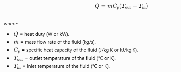
For a hot stream undergoing cooling, the temperature difference is negative if expressed as outlet minus inlet. In practice, the magnitude of the heat removed is commonly reported as a positive duty.For example, consider a process stream with a mass flow rate of 10 kg/s and a specific heat capacity of 2.5 kJ/(kg·K), cooled from 120°C to 80°C.
The heat removed is:
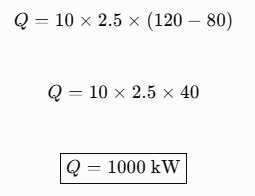
The exchanger is therefore removing approximately 1 MW of thermal energy, assuming steady operation and negligible heat losses.
This calculation becomes especially valuable when comparing current performance with a historical baseline. If the inlet temperature, flow rate, and required outlet temperature remain similar but the measured duty falls, the exchanger may be experiencing thermal deterioration or a flow-related limitation.
However, a lower duty does not automatically prove fouling. The process may simply be receiving less heat, operating at a lower flow rate, or experiencing a change in its boundary conditions.
Where phase changes oyou may also need to consider temperature-dependent properties and composition changesccur, such as boiling or condensation, the energy balance must account for latent heat and, where relevant, sensible heating or cooling. For complex mixtures, temperature-dependent properties and composition changes may also need to be considered.
1.2 The overall heat-transfer coefficient: A measure of thermal resistance
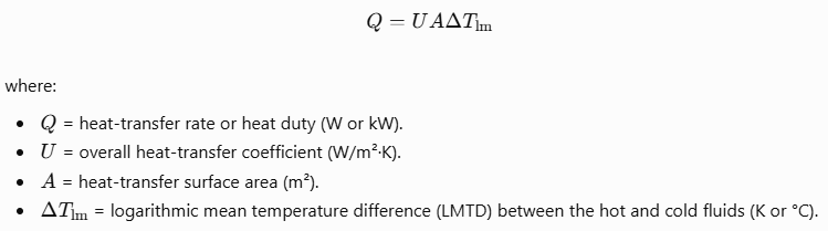
For a conventional exchanger operating without a phase change, the heat-transfer rate can be expressed as:
For counter-current flow:
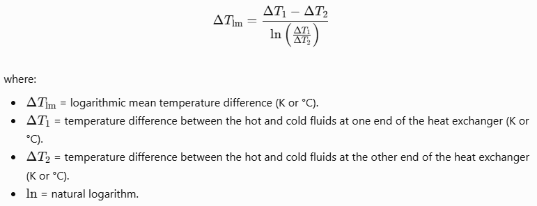
For multipass shell-and-tube exchangers and other configurations that deviate from ideal counter-current flow, the correction factor must be evaluated appropriately. Temperature crosses, phase changes, and complex flow arrangements require additional care.
The overall heat-transfer coefficient reflects the combined thermal resistances of the hot-side film, cold-side film, exchanger wall, and any deposits on the heat-transfer surfaces. Fouling adds resistance and can reduce the overall coefficient.
A useful troubleshooting relationship is:
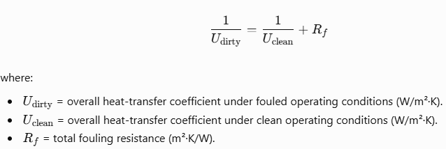
This simplified relationship assumes a consistent area basis and an additive fouling resistance. More rigorous calculations may be required when inner and outer surface areas differ, wall resistance is significant, or the individual resistances change with operating conditions.
The practical implication is important: a decrease in the overall heat-transfer coefficient can indicate additional thermal resistance, but it does not identify the cause by itself. Changes in flow velocity, fluid properties, phase distribution, and operating conditions can also affect the coefficient.
2. Fouling: The Hidden Resistance That Gradually Reduces Performance
Fouling occurs when unwanted material accumulates on heat-transfer surfaces or when deposits form through physical, chemical, or biological processes. It is one of the most common causes of declining exchanger performance, but its behaviour varies considerably across applications.
2.1 Understanding the major fouling mechanisms
In petroleum and chemical processing, fouling may involve polymerization, coke formation, heavy hydrocarbon deposits, corrosion products, or precipitation of poorly soluble compounds. In cooling-water systems, mineral scaling, suspended solids, corrosion products, and biological growth may become significant.
Food and pharmaceutical applications may experience protein deposits, crystallized products, or residues from inadequate cleaning. Wastewater and contaminated process streams may introduce fibres, particulates, and other materials that obstruct flow passages.
Different mechanisms produce different symptoms and require different corrective actions.
Mineral scaling may reduce heat transfer while progressively restricting passages. Particulate deposition may increase pressure drop and create uneven flow distribution. Biological fouling may develop unevenly and can be particularly difficult to manage where water treatment is inadequate. High-temperature hydrocarbon fouling may produce hard deposits that require specialized cleaning or process-condition changes to control.
It is therefore a mistake to assume that every exchanger should be cleaned using the same chemical, mechanical method, or maintenance interval.
Before selecting a cleaning method, engineers should identify the likely deposit composition, material compatibility, operating conditions, environmental requirements, and potential consequences of disturbing the deposit.
2.2 How to distinguish fouling from other causes of performance loss
A fouling diagnosis becomes more convincing when several independent indicators point toward increased resistance or restricted flow.
For example, a declining calculated heat-transfer coefficient, increasing pressure drop at comparable flow rates, and a worsening outlet-temperature approach may collectively indicate fouling. The interpretation becomes stronger when the trend develops gradually and corresponds to known deposit-forming conditions.
However, pressure drop does not always increase as fouling progresses. Some deposits primarily affect heat transfer, while others obstruct only part of the flow path. Changes in flow rate can also conceal or exaggerate the hydraulic effect.
Similarly, a lower calculated heat-transfer coefficient may arise from reduced Reynolds number, changing viscosity, inaccurate flow measurements, or incorrect temperature readings.
A useful diagnostic practice is to compare the exchanger with its own clean or recently verified performance under comparable conditions. If a clean baseline is unavailable, engineers should establish a defensible reference using design calculations, historical operating records, or a validated thermal rating model.
The objective is to separate three questions:
- Has the exchanger's actual heat-transfer performance deteriorated?
- Is the deterioration caused by increased thermal resistance, reduced effective area, altered flow distribution, or changed operating conditions?
- Does the evidence justify cleaning, a process adjustment, a mechanical modification, or further investigation?
Answering these questions prevents maintenance teams from treating symptoms while leaving the underlying cause unresolved.
3. Recognizing the Warning Signs of Heat Exchanger Underperformance
Performance loss often develops gradually. Monitoring only whether the exchanger is meeting its immediate temperature target can conceal deterioration because control systems may compensate by increasing utility flow, adjusting bypass valves, or reducing throughput elsewhere in the process.A more effective approach is to examine thermal, hydraulic, operational, and economic indicators together.
Thermal warning signs
A rising process outlet temperature on a cooler, or a falling outlet temperature on a heater, may indicate reduced heat transfer. A decreasing temperature approach can be particularly important when the process is already operating near its thermal limit.For condensers, declining condensation performance may appear as a higher outlet temperature, reduced condensation rate, elevated downstream pressure, or unstable operation. Non-condensable gases can also impair condensation, meaning that cleaning the heat-transfer surfaces may not solve the problem.For reboilers, inadequate heat input may limit column throughput, affect product purity, or increase the energy required to achieve the desired separation.
Hydraulic warning signs
Increasing pressure drop across the exchanger may indicate passage restriction, deposition, maldistribution, or changes in fluid properties. Conversely, an unexpected decrease in pressure drop can signal bypassing, internal leakage, flow redistribution, or a reduction in actual flow.Engineers should compare pressure drop at equivalent flow rates or use an appropriate hydraulic model to normalize the comparison. Pressure drop alone is not a reliable fouling indicator.
Operational and economic warning signs
Other indicators include increasing cooling-water demand, rising steam consumption, higher pumping power, repeated control-valve adjustments, reduced production rates, more frequent cleaning, and unstable downstream process conditions.
These symptoms often reveal the commercial consequences of exchanger deterioration. A unit that still achieves its target outlet temperature may nevertheless be operating inefficiently because the control system compensates with additional utilities or because another piece of equipment must work harder.
The most valuable monitoring systems therefore track not only whether the exchanger meets its process target, but also the resources required to achieve it.
4. A Systematic Heat Exchanger Troubleshooting Method
Effective troubleshooting should proceed from data validation to thermal analysis, hydraulic assessment, root-cause investigation, and corrective action. This sequence reduces the risk of unnecessary shutdowns and prevents engineers from committing to a costly intervention before establishing the cause of the problem.
Step 1: Validate the operating data
Begin by collecting the hot- and cold-side inlet and outlet temperatures, mass or volumetric flow rates, inlet and outlet pressures, fluid composition, and relevant physical properties.
Also establish the exchanger configuration, design duty, heat-transfer area, design pressure drop, historical clean performance, and current operating limits.
Instrument quality is critical. A temperature sensor with a systematic bias can create the appearance of deteriorating performance. Flowmeters may be inaccurate outside their calibrated range, while pressure transmitters can drift or develop plugged impulse lines.
Check whether measurements are taken simultaneously and whether the process is operating at steady state. If the exchanger is experiencing rapidly changing load, a simple steady-state energy balance may produce misleading results.
Where possible, calculate heat duty independently from both fluid sides:
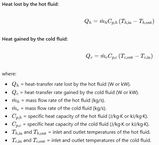
Under steady conditions, the two duties should be reasonably consistent after accounting for heat losses, measurement uncertainty, and the limitations of the property estimates.A substantial discrepancy indicates that the data, assumptions, or energy balance require investigation. It should not automatically be interpreted as a fouling problem.
Step 2: Establish the actual thermal performance
Calculate the heat duty, log mean temperature difference, and overall heat-transfer coefficient using a consistent calculation basis.
Compare the results with the design case and, preferably, with historical performance at comparable flow rates, inlet temperatures, fluid properties, and operating conditions.
This comparison is more meaningful than comparing raw outlet temperatures alone. For example, a lower duty may be entirely appropriate if the process feed rate has decreased. Conversely, a unit may show apparently normal duty while requiring substantially more cooling water than before.
For monitoring purposes, a normalized performance indicator can help distinguish genuine deterioration from changes in operating conditions. The normalization method should be appropriate for the exchanger configuration and should not assume that the heat-transfer coefficient remains constant with flow rate.
Step 3: Evaluate the hydraulic performance
Calculate the pressure drop across each side of the exchanger and compare it with the expected clean hydraulic performance.
Where the geometry and fluid properties are known, evaluate the effects of flow velocity, Reynolds number, viscosity, density, and passage geometry.
A rising pressure drop at comparable flow may suggest fouling or obstruction. If pressure drop remains normal while the thermal coefficient declines, the investigation may need to focus on deposits that primarily affect thermal resistance, incorrect flow distribution, non-condensable gases, or measurement errors.
The analysis should also consider the wider system. A pump operating away from its intended operating point, a partially closed valve, a blocked strainer, or inadequate utility supply may prevent the exchanger from receiving the flow required for its design duty.
Step 4: Investigate the root cause
Once the performance loss has been verified, identify the mechanism responsible.
Review the history of feed composition, temperature, flow, cooling-water quality, chemical dosing, cleaning frequency, and process upsets. Examine whether changes in operating conditions have increased the tendency for precipitation, polymerization, biological growth, corrosion, or particulate deposition.
Where justified, inspect the exchanger internally during a planned shutdown. Deposit samples, photographs, tube inspection, and evidence of corrosion or erosion can help distinguish between competing explanations.
For shell-and-tube exchangers, inspect relevant tubes, tube sheets, baffles, seals, and flow-distribution components. For plate heat exchangers, investigate blocked channels, damaged gaskets, plate deformation, and incorrect assembly. Other exchanger designs require inspection procedures suited to their construction.
The objective is not merely to confirm that deposits exist. It is to understand why they formed and whether the operating conditions or equipment design need to change to prevent recurrence.
Step 5: Select and verify the corrective action
Possible actions include cleaning, restoring flow distribution, repairing leaking or damaged components, correcting instrumentation, adjusting operating conditions, improving water treatment, or modifying the exchanger.
After the intervention, verify the result using comparable operating conditions and the same performance indicators used during diagnosis.
A successful maintenance intervention should demonstrate measurable recovery in thermal performance, acceptable pressure drop, stable operation, and, where applicable, reduced utility consumption.
Without post-maintenance verification, it is difficult to determine whether the action solved the problem or merely provided temporary relief.
5. Cleaning Decisions: When Is Maintenance Actually Worthwhile?
Cleaning is often the first intervention considered when a heat exchanger underperforms. However, cleaning introduces direct costs, production losses, labour requirements, waste disposal obligations, and potential risks to equipment integrity.
The decision should therefore be based on the expected benefit, not simply on elapsed operating time.
Thermal and mechanical cleaning
Mechanical cleaning may be appropriate for deposits that can be removed using suitable brushing, scraping, or water-jetting methods. Chemical cleaning may be effective for particular mineral scales, corrosion products, or other deposits when the chemistry is compatible with the exchanger materials.
The method must be selected with care. Incompatible cleaning chemicals, excessive pressure, unsuitable tools, or poor control of cleaning conditions can damage tubes, plates, gaskets, coatings, and other components.
Cleaning should also be performed under an approved isolation, depressurization, draining, and equipment-opening procedure, with appropriate control of hazardous residues and waste.
The economics of cleaning
Consider an exchanger that has lost a portion of its useful thermal capacity. If this loss increases energy consumption or limits production, the financial impact may be substantial.
The annual cost of underperformance can be approximated as:
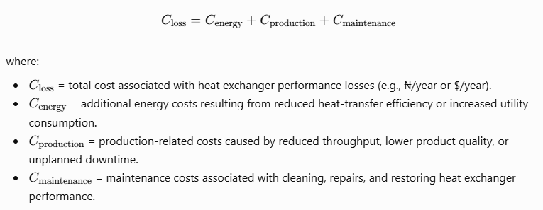
where the terms represent the incremental costs attributable to energy consumption, lost production, and additional maintenance. These components should be defined carefully to avoid double counting.
The economic benefit of cleaning can then be estimated by comparing the expected recovery in performance against the total cleaning cost, including downtime and any associated production losses.
For example, if cleaning costs $8,000 and is expected to avoid $2,000 per month in demonstrable incremental operating costs, the simple payback period is:
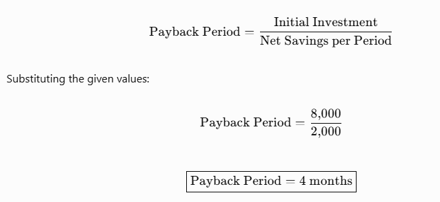
This is a simplified illustration, not a universal cleaning threshold. Actual decisions should account for uncertainty in recovered performance, the duration of the benefit, future fouling rates, the cost of a shutdown, and the remaining equipment life.
A particularly important question is whether cleaning will restore the original performance. If the real constraint is inadequate exchanger area, poor distribution, a utility bottleneck, or an incorrectly specified design duty, cleaning alone will not provide a lasting solution.
6. Heat Exchanger Debottlenecking: Recovering Capacity Beyond Routine Cleaning
Debottlenecking is the systematic identification and removal of constraints that prevent a process unit from achieving its desired throughput, efficiency, or product specification.
In heat exchanger systems, the limiting factor may be the exchanger itself, but it may also be the utility system, upstream equipment, downstream process requirements, pressure-drop limits, control valves, or the operating envelope of associated machinery.
A technically sound debottlenecking study therefore examines the exchanger as part of the complete process system.
6.1 Establish the actual process bottleneck
Start by defining the production or performance target. Is the objective to increase feed throughput, reduce cooling-water consumption, increase product recovery, improve distillation performance, or maintain production during seasonal temperature changes?
Next, determine which constraint prevents the target from being achieved.
A heat exchanger may be thermally limited because its available area is insufficient at the required duty. It may be hydraulically limited because the required flow would exceed an allowable pressure drop. Alternatively, the exchanger may have sufficient capacity but be constrained by inadequate cooling-water supply or a downstream equipment limit.
For example, increasing exchanger area will not necessarily increase production if a downstream separator, distillation column, pump, or compressor is already at its operating limit.
The best debottlenecking opportunities arise when the engineering team identifies the controlling constraint rather than simply upgrading the most visible equipment.
6.2 Improve thermal performance before adding new equipment
Several interventions can improve existing exchanger performance, depending on the diagnosed limitation.
Restoring cleanliness may recover lost heat-transfer capacity. Correcting bypass leakage or flow maldistribution may improve the effective use of available surface area. Improving cooling-water quality may reduce the rate of future scaling. Adjusting flow distribution or operating conditions may increase the heat-transfer coefficient where hydraulic and process limits permit.
However, increasing flow is not automatically beneficial. Higher velocity can improve convective heat transfer in some operating regimes, but it also increases pressure drop and pumping requirements. It may introduce erosion, vibration, or other mechanical concerns, particularly at high velocities or in vulnerable geometries.
Any proposed adjustment should therefore be evaluated using both thermal and hydraulic calculations.
6.3 Evaluate additional surface area or exchanger replacement
If the existing exchanger is clean, operating correctly, and still unable to meet the required duty, additional heat-transfer area may be necessary.
Possible options include installing a larger exchanger, adding a parallel unit, replacing the existing exchanger with a higher-capacity design, or modifying the arrangement of the exchanger network.
A parallel exchanger may increase total capacity while allowing individual units to be isolated for maintenance, although the actual benefit depends on flow distribution and system design.
A replacement exchanger may offer improved thermal performance, but the study must consider pressure drop, material compatibility, maintenance accessibility, utility availability, footprint, and capital cost.
It is also important to assess whether a more compact design is appropriate. For example, a plate heat exchanger may offer high heat-transfer area per unit volume in suitable services, but it may not be appropriate for every pressure, temperature, fouling, solids-loading, or maintenance requirement.
6.4 Optimize the wider heat exchanger network
Some of the largest savings come from evaluating several exchangers together rather than improving each unit in isolation.
Pinch analysis and heat exchanger network optimization can reveal opportunities to recover heat from hot process streams and use it to preheat colder streams. This can reduce steam demand, cooling-water consumption, and the need for additional utility equipment.
Nevertheless, network modifications must account for controllability, operating flexibility, start-up and shutdown conditions, cross-contamination risks, and the consequences of equipment failure.
The objective is to optimize the overall process, not simply maximize heat recovery in an individual exchanger.
7. Using Engineering Calculations to Quantify Debottlenecking Opportunities
Engineering calculations help translate observed performance problems into defensible decisions about cleaning, operating changes, and capital investment.
A heat exchanger rating calculation estimates the performance of a defined exchanger geometry under specified operating conditions. A design calculation, by contrast, determines the exchanger characteristics required to meet a specified duty and operating envelope.
These are related but distinct tasks. A rating calculation may demonstrate that the existing unit cannot meet the required duty under current conditions, while a design study can evaluate the area, configuration, and hydraulic requirements of a proposed replacement.A useful engineering assessment should evaluate at least three cases:
Case 1: Current operating performance. Establish the actual heat duty, thermal approach, pressure drop, and operating constraints using validated data.
Case 2: Clean or restored performance. Estimate the capacity that could be recovered if fouling, flow distribution, or other identified defects were corrected.
Case 3: Proposed debottlenecking modification. Evaluate the thermal and hydraulic performance of the modified exchanger or network, including the required utilities and operating limits.
Comparing these cases makes it possible to quantify the value of maintenance relative to equipment modification.
For example, if restoring the clean performance of an existing exchanger achieves the required duty, replacement may not be necessary. If the clean exchanger still cannot meet the target, a design upgrade or process modification may be justified.
The assessment should also include uncertainty ranges where operating data, fluid properties, fouling resistance, or future process conditions are not known precisely. This is especially important when the business case depends on a small predicted improvement or when the consequences of underperformance are significant.
8. Common Troubleshooting Mistakes That Waste Time and Money
Several recurring mistakes prevent organisations from resolving exchanger performance problems effectively.
The first is diagnosing fouling from outlet temperatures alone. Outlet temperatures depend on flow rates, inlet conditions, heat capacities, utility availability, and the exchanger's thermal performance. Without these additional measurements, the root cause remains uncertain.
The second is increasing flow without evaluating pressure drop and mechanical limits. This may shift the problem to a pump, control valve, utility header, or downstream process unit, while increasing energy consumption.
The third is cleaning repeatedly without investigating why fouling occurs. Where deposit formation is driven by poor water treatment, unsuitable operating temperatures, chemical instability, or excessive solids loading, repeated cleaning treats the consequence rather than the cause.
The fourth is replacing an exchanger before evaluating the complete system. The true limitation may be a control valve, a utility supply problem, incorrect instrumentation, or a downstream process constraint.
Finally, organisations sometimes fail to document a verified clean baseline. Without reliable historical data, each subsequent investigation becomes more difficult, and the maintenance team loses the ability to quantify deterioration or determine the appropriate cleaning interval.
These mistakes can be reduced through consistent data collection, validated thermal and hydraulic models, documented maintenance history, and performance verification after every major intervention.
9. Building a Proactive Heat Exchanger Performance Monitoring System
The most effective troubleshooting strategy is one that detects deterioration before it becomes a production constraint.
A practical monitoring programme should record the relevant inlet and outlet temperatures, flow rates, pressure drops, process duty, and utility consumption at defined intervals. Where the consequences of failure are high, online monitoring and automated calculations may be justified.
The monitoring system should compare operating performance against an appropriate baseline and account for changes in flow rate, inlet temperature, fluid properties, and other relevant conditions.
For example, a rising pressure drop combined with declining normalized thermal performance may justify an inspection or cleaning assessment. A declining heat-transfer coefficient without a corresponding hydraulic change may indicate a different fouling mechanism, altered heat-transfer conditions, or an instrumentation issue.
The response should be based on engineering thresholds and trends rather than a single isolated measurement.
A useful performance dashboard may include heat duty, normalized overall heat-transfer coefficient, pressure drop on each side, utility consumption per unit of production, frequency of cleaning, and the estimated economic impact of underperformance.
Over time, this information can support condition-based maintenance, improve outage planning, and provide evidence for capital investment decisions.
10. Safety and Reliability Considerations During Troubleshooting
Heat exchanger troubleshooting must be conducted within the limits of approved operating procedures, equipment design conditions, and site safety requirements.
Increasing pressure, temperature, flow, or utility loading to recover performance can create new hazards if the system is already near its mechanical or process limits. Similarly, opening a fouled exchanger can expose personnel to hazardous process fluids, pressurized residues, corrosive deposits, or toxic cleaning chemicals.
Before inspection or maintenance, appropriate isolation, depressurization, draining, purging, and verification procedures must be followed. Where hazardous energy sources are present, the relevant lockout and isolation requirements should be applied.
Any proposed debottlenecking modification should also be assessed for its impact on pressure drop, control stability, relief-system requirements, mechanical integrity, vibration, and downstream operating conditions.
Where a modification changes the process design basis or equipment operating envelope, the organisation should follow its formal engineering review and management-of-change procedures.
A successful intervention is not simply one that restores capacity. It must do so without compromising safety, reliability, product quality, or the integrity of the wider plant.
Conclusion: Turn Heat Exchanger Troubleshooting into a Performance Improvement Opportunity
Heat exchanger performance loss should not be treated as an inevitable maintenance problem. It is an opportunity to improve process reliability, reduce energy consumption, recover production capacity, and make better capital investment decisions.
The most effective approach begins with reliable operating data, a validated energy balance, and a clear understanding of thermal and hydraulic performance. Engineers can then distinguish fouling from other causes, identify the actual bottleneck, and compare the benefits of cleaning, operating adjustments, equipment modification, and heat recovery optimization.
The long-term objective is to move beyond reactive maintenance toward a data-driven approach in which exchanger performance is continuously evaluated against process requirements and economic objectives.
For process engineers, maintenance teams, and plant managers, the central question is not merely whether a heat exchanger is underperforming. It is how much performance has been lost, what is causing the loss, how much can realistically be recovered, and which intervention delivers the greatest value without compromising safety or reliability.
With systematic troubleshooting and sound engineering calculations, heat exchangers can become more than equipment that must be maintained. They can become measurable opportunities for operational improvement.
Take the Next Step with Delflow
Effective heat exchanger troubleshooting requires more than observing temperatures and pressure drops. It requires a structured evaluation of heat duty, thermal resistance, pressure drop, design limitations, and operating economics.
Delflow's heat exchanger engineering resources can support engineers in organizing design calculations, evaluating operating performance, investigating capacity limitations, and assessing potential debottlenecking opportunities.
Explore the relevant engineering design and calculation tools at Delflow to support more informed equipment evaluation and process optimization decisions.